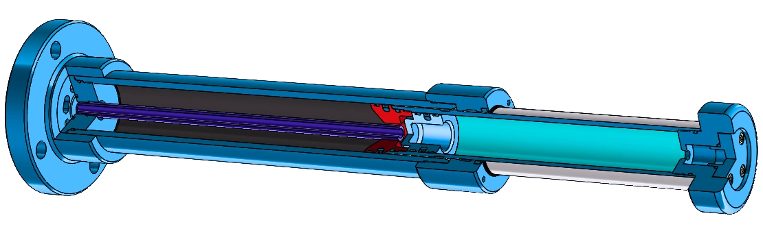
Hydraulic Buffer
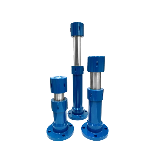
Advanced hydraulic buffer systems designed for high-energy impact absorption in crane and rail transport systems. These crane buffers effectively dampen collision-induced energy, ensuring system longevity and safety while preventing structural damage from unabsorbed kinetic energy.
Key Features
Technical Specifications
| Construction | Heavy-duty steel construction with hydraulic cylinder |
| Dimensions | Custom sizes available (100-800mm stroke) |
| Weight | Varies by capacity (10-500kg) |
| Certification | CE certified, ISO 9001 |
| Energy Absorption | Up to 50,000 Nm energy absorption |
| Stroke Range | 100-800mm adjustable stroke |
| Connection Type | Flange, threaded, or custom connections |
| Operating Temperature | -20°C to +80°C operating range |
HB 100
| Model | S | L | L1 | L2 | B | D1 | D2 | D3 | d | W (kJ) | F (kN) |
|---|---|---|---|---|---|---|---|---|---|---|---|
| HB 100 100 | 100 | 538.5 | 207 | 301.5 | 30 | 132 | 258 | 210 | 23 | 38 | 420 |
| HB 100 150 | 150 | 651 | 257 | 364 | 30 | 132 | 258 | 210 | 23 | 58 | 420 |
| HB 100 200 | 200 | 763.5 | 307 | 426.5 | 30 | 132 | 258 | 210 | 23 | 78 | 420 |
| HB 100 250 | 250 | 876 | 357 | 489 | 30 | 132 | 258 | 210 | 23 | 98 | 420 |
| HB 100 300 | 300 | 988.5 | 407 | 551.5 | 30 | 132 | 258 | 210 | 23 | 115 | 420 |
| HB 100 350 | 350 | 1101 | 457 | 614 | 30 | 132 | 258 | 210 | 23 | 132 | 420 |
| HB 100 400 | 400 | 1213.5 | 507 | 676.5 | 30 | 132 | 258 | 210 | 23 | 148 | 410 |
| HB 100 450 | 450 | 1326 | 557 | 739 | 30 | 132 | 258 | 210 | 23 | 161 | 400 |
| HB 100 500 | 500 | 1438.5 | 607 | 801.5 | 30 | 132 | 258 | 210 | 23 | 175 | 390 |
| HB 100 550 | 550 | 1551 | 657 | 864 | 30 | 132 | 258 | 210 | 23 | 190 | 380 |
| HB 100 600 | 600 | 1663.5 | 707 | 926.5 | 30 | 132 | 258 | 210 | 23 | 200 | 370 |
| HB 100 650 | 650 | 1776 | 757 | 989 | 30 | 132 | 258 | 210 | 23 | 210 | 360 |
| HB 100 700 | 700 | 1888.5 | 807 | 1051.5 | 30 | 132 | 258 | 210 | 23 | 220 | 350 |
| HB 100 750 | 750 | 2001 | 857 | 1114 | 30 | 132 | 258 | 210 | 23 | 230 | 340 |
| HB 100 800 | 800 | 2113.5 | 907 | 1176.5 | 30 | 132 | 258 | 210 | 23 | 240 | 330 |
HB 125
| Model | S | L | L1 | L2 | B | D1 | D2 | D3 | d | W (kJ) | F (kN) |
|---|---|---|---|---|---|---|---|---|---|---|---|
| HB 125 100 | 100 | 528.5 | 204.5 | 289 | 35 | 167 | 300 | 245 | 27 | 60 | 670 |
| HB 125 150 | 150 | 641 | 254.5 | 351.5 | 35 | 167 | 300 | 245 | 27 | 91 | 670 |
| HB 125 200 | 200 | 753.5 | 304.5 | 414 | 35 | 167 | 300 | 245 | 27 | 121 | 670 |
| HB 125 250 | 250 | 866 | 354.5 | 476.5 | 35 | 167 | 300 | 245 | 27 | 154 | 670 |
| HB 125 300 | 300 | 978.5 | 404.5 | 539 | 35 | 167 | 300 | 245 | 27 | 185 | 670 |
| HB 125 350 | 350 | 1091 | 454.5 | 601.5 | 35 | 167 | 300 | 245 | 27 | 215 | 670 |
| HB 125 400 | 400 | 1203.5 | 504.5 | 664 | 35 | 167 | 300 | 245 | 27 | 248 | 670 |
| HB 125 450 | 450 | 1316 | 554.5 | 726.5 | 35 | 167 | 300 | 245 | 27 | 275 | 650 |
| HB 125 500 | 500 | 1428.5 | 604.5 | 789 | 35 | 167 | 300 | 245 | 27 | 301 | 650 |
| HB 125 550 | 550 | 1541 | 654.5 | 851.5 | 35 | 167 | 300 | 245 | 27 | 325 | 630 |
| HB 125 600 | 600 | 1653.5 | 704.5 | 914 | 35 | 167 | 300 | 245 | 27 | 351 | 630 |
| HB 125 650 | 650 | 1766 | 754.5 | 976.5 | 35 | 167 | 300 | 245 | 27 | 377 | 630 |
| HB 125 700 | 700 | 1878.5 | 804.5 | 1039 | 35 | 167 | 300 | 245 | 27 | 393 | 610 |
| HB 125 750 | 750 | 1991 | 854.5 | 1101.5 | 35 | 167 | 300 | 245 | 27 | 414 | 610 |
| HB 125 800 | 800 | 2103.5 | 904.5 | 1164 | 35 | 167 | 300 | 245 | 27 | 435 | 590 |
HB 063
| Model | S | L | L1 | L2 | B | D1 | D2 | D3 | d | W (kJ) | F (kN) |
|---|---|---|---|---|---|---|---|---|---|---|---|
| HB 063 100 | 100 | 455.5 | 202 | 233.5 | 20 | 91 | 168 | 135 | 17 | 15 | 170 |
| HB 063 150 | 150 | 568 | 252 | 296 | 20 | 91 | 168 | 135 | 17 | 23 | 170 |
| HB 063 200 | 200 | 680.5 | 302 | 358.5 | 20 | 91 | 168 | 135 | 17 | 30 | 170 |
| HB 063 250 | 250 | 793 | 352 | 421 | 20 | 91 | 168 | 135 | 17 | 38 | 170 |
| HB 063 300 | 300 | 905.5 | 402 | 483.5 | 20 | 91 | 168 | 135 | 17 | 46 | 170 |
| HB 063 350 | 350 | 1018 | 452 | 546 | 20 | 91 | 168 | 135 | 17 | 51 | 160 |
| HB 063 400 | 400 | 1130.5 | 502 | 608.5 | 20 | 91 | 168 | 135 | 17 | 54 | 150 |
| HB 063 450 | 450 | 1243 | 552 | 671 | 20 | 91 | 168 | 135 | 17 | 57 | 140 |
| HB 063 500 | 500 | 1355.5 | 602 | 733.5 | 20 | 91 | 168 | 135 | 17 | 59 | 130 |
| HB 063 550 | 550 | 1468 | 652 | 796 | 20 | 91 | 168 | 135 | 17 | 60 | 120 |
| HB 063 600 | 600 | 1580.5 | 702 | 858.5 | 20 | 91 | 168 | 135 | 17 | 60 | 110 |
| HB 063 650 | 650 | 1693 | 752 | 921 | 20 | 91 | 168 | 135 | 17 | 59 | 100 |
| HB 063 700 | 700 | 1805.5 | 802 | 983.5 | 20 | 91 | 168 | 135 | 17 | 57 | 90 |
| HB 063 750 | 750 | 1918 | 852 | 1046 | 20 | 91 | 168 | 135 | 17 | 54 | 80 |
| HB 063 800 | 800 | 2030.5 | 902 | 1108.5 | 20 | 91 | 168 | 135 | 17 | 51 | 70 |
HB 080
| Model | S | L | L1 | L2 | B | D1 | D2 | D3 | d | W (kJ) | F (kN) |
|---|---|---|---|---|---|---|---|---|---|---|---|
| HB 080 100 | 100 | 522.5 | 209.5 | 288 | 25 | 110 | 198 | 165 | 17 | 23 | 260 |
| HB 080 150 | 150 | 635 | 259.5 | 350.5 | 25 | 110 | 198 | 165 | 17 | 35 | 260 |
| HB 080 200 | 200 | 747.5 | 309.5 | 413 | 25 | 110 | 198 | 165 | 17 | 48 | 260 |
| HB 080 250 | 250 | 860 | 359.5 | 475.5 | 25 | 110 | 198 | 165 | 17 | 59 | 260 |
| HB 080 300 | 300 | 972.5 | 409.5 | 538 | 25 | 110 | 198 | 165 | 17 | 68 | 250 |
| HB 080 350 | 350 | 1085 | 459.5 | 600.5 | 25 | 110 | 198 | 165 | 17 | 76 | 240 |
| HB 080 400 | 400 | 1197.5 | 509.5 | 663 | 25 | 110 | 198 | 165 | 17 | 84 | 230 |
| HB 080 450 | 450 | 1310 | 559.5 | 725.5 | 25 | 110 | 198 | 165 | 17 | 90 | 220 |
| HB 080 500 | 500 | 1422.5 | 609.5 | 788 | 25 | 110 | 198 | 165 | 17 | 95 | 210 |
| HB 080 550 | 550 | 1535 | 659.5 | 850.5 | 25 | 110 | 198 | 165 | 17 | 100 | 200 |
| HB 080 600 | 600 | 1647.5 | 709.5 | 913 | 25 | 110 | 198 | 165 | 17 | 104 | 190 |
| HB 080 650 | 650 | 1760 | 759.5 | 975.5 | 25 | 110 | 198 | 165 | 17 | 106 | 180 |
| HB 080 700 | 700 | 1872.5 | 809.5 | 1038 | 25 | 110 | 198 | 165 | 17 | 108 | 170 |
| HB 080 750 | 750 | 1985 | 859.5 | 1100.5 | 25 | 110 | 198 | 165 | 17 | 109 | 160 |
| HB 080 800 | 800 | 2097.5 | 909.5 | 1163 | 25 | 110 | 198 | 165 | 17 | 109 | 150 |
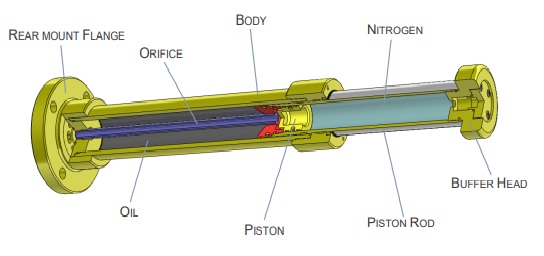
Internal Structure
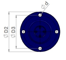
Flange Mounting
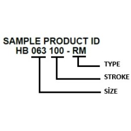
Product ID Structure
Mounting Types
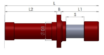
TYPE FM (Front Mount)
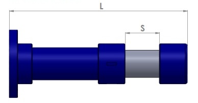
TYPE RM (Rear Mount)

Flange Type
Application
Conditions
Color
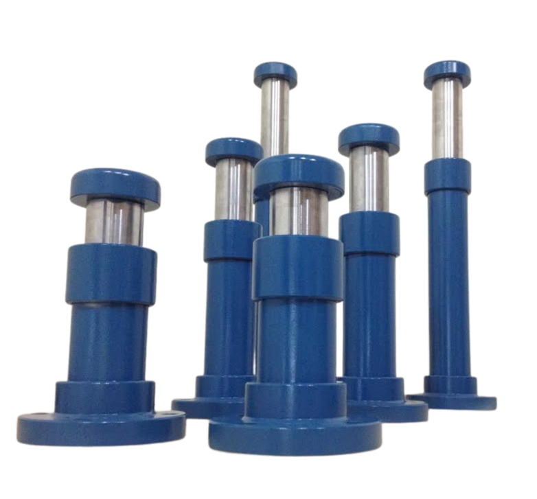
KRANHAUSS HB series hydraulic crane buffers absorb the kinetic energy of a crane or trolley reaching the end of its runway and convert it into heat through controlled hydraulic damping. The series spans four body sizes — HB 063, HB 080, HB 100 and HB 125 — each in 15 stroke lengths from 100 mm to 800 mm in 50 mm steps: 60 standard models in total. Energy absorption per stroke ranges from 15 to 435 kJ, with buffering forces up to 670 kN. Every buffer is made to order in Ankara and sized to your crane's actual mass and speed.
How to Select a Hydraulic Crane Buffer: Energy, Force and Stroke
Selection starts with the kinetic energy the buffer must absorb, calculated from the moving mass and the speed at the moment of impact. Compare that figure in kJ with the energy absorption capacity (W) listed for each model in the tables above; the chosen model must exceed the calculated energy with a sensible margin.
The second check is force: the buffering force (F) column shows the load the buffer transmits into the end stop and runway structure during impact — the number your structural engineer will ask for. Within a body size, a longer stroke gives a longer deceleration distance, gentler retardation and lower structural force: in the HB 100 size, force falls from 420 kN at 100 mm stroke to 330 kN at 800 mm. The model designation encodes this logic — HB 100 500 is body size 100 with a 500 mm stroke (175 kJ, 390 kN).
Applications: Overhead, Gantry, Port and Steel-Mill Cranes
HB buffers are fitted to overhead (bridge) cranes, gantry and semi-gantry cranes, port and shipyard cranes, and heavy-duty process cranes in steel mills. They mount either on the crane end carriage or on the end stop at the rail end, and the same series covers cross-travel: a trolley sees a different mass and speed than the long-travel motion, so bridge and trolley buffers should be sized independently using the same tables.
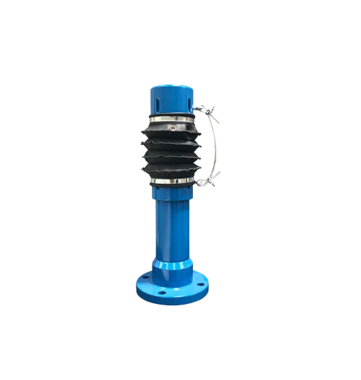
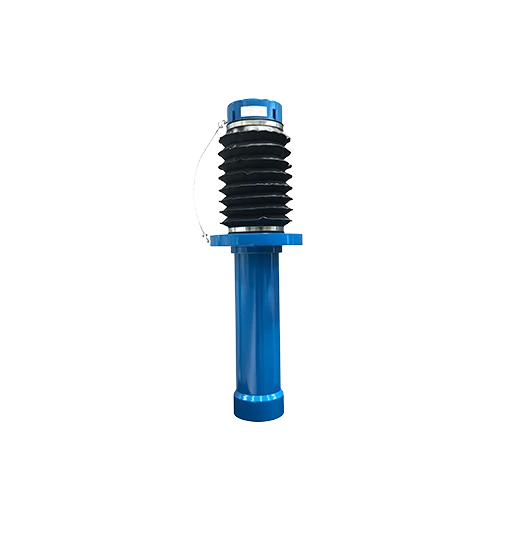
Each model is configured for indoor or outdoor service at order, with a separate environment option beyond the normal configuration for aggressive conditions such as coastal sites, chemical plants or heavy dust. With four body sizes covering 15 to 435 kJ, the range runs from light workshop cranes to the heaviest end-of-travel duties.
Hydraulic vs Spring vs Polyurethane Buffers: An Honest Comparison
We manufacture all three buffer types, so this comparison has no agenda. Polyurethane buffers are the economical, maintenance-free choice for standard indoor cranes at modest speeds and energies. Spring buffers handle more energy but store it rather than dissipate it — the stored energy throws the crane back on rebound, which can aggravate load swing.
A hydraulic buffer converts impact energy into heat as oil is forced through calibrated metering orifices: rebound is negligible, deceleration stays controlled and nearly uniform across the stroke, and the energy capacity for a given buffer size is the highest of the three — up to 435 kJ in the HB series. For fast long-travel cranes, heavy masses, ports and steel mills, hydraulic is the right call; for light, slow indoor duty, polyurethane or spring buffers may be all you need.
Ordering and Customization: FM/RM Mounting, Colors, Custom Strokes
Every HB buffer is built to order. Two mounting arrangements are available — Front Mount (FM) and Rear Mount (RM) — and the diagrams above show both layouts together with flange dimensions and bolt-hole patterns. Six standard colors let the buffer match plant color codes or visibility requirements.
If your application falls outside the 60 standard models — a custom stroke, a different flange drilling, or a like-for-like replacement for an existing buffer — our engineering team defines the matching unit with you from your measured dimensions and duty data. KRANHAUSS has manufactured crane components in Ankara since 2004 and exports to more than 50 countries, with certifications including ISO 9001, ISO 3834-2 and EN 1090.
Frequently Asked Questions
How do I choose the right stroke length?
Within a body size, a longer stroke means a longer braking distance: the crane stops more gently and the force passed into the end stop and runway drops. Choose longer strokes for higher travel speeds or where the structure's force capacity is limited. The tables above list energy (W) and force (F) for every stroke — read both columns together when selecting.
What is the difference between Front Mount (FM) and Rear Mount (RM)?
An FM buffer bolts up by its front flange, an RM buffer by its rear flange. The choice depends on the connection surface and the space available on the end carriage or end stop. Both arrangements are fully dimensioned in the mounting diagrams above, including L1/L2 lengths and the flange bolt pattern.
Should the suspended load be included in the kinetic energy calculation?
Common engineering practice excludes a load hanging freely on hoist ropes from the impact energy calculation, while rigidly guided loads are added to the moving mass. Your project specification may require a different assumption, so verify the final calculation against the applicable design documents.
Can HB buffers be used outdoors or in aggressive environments?
Yes. Each model is configured at order for indoor or outdoor service, and alongside the normal configuration a separate option covers aggressive environments such as coastal, chemical or high-dust sites. Specifying the operating environment when ordering is enough — the buffer is configured and built accordingly.
How do I replace an existing buffer of unknown make?
Measure the stroke, the overall length (L), the flange and bolt-circle diameters (D2/D3) and the bolt-hole size (d), and record the crane mass and travel speed. Compare these against the tables above to find the equivalent HB model. If nothing matches exactly, a custom stroke or flange drilling can be produced to your measured dimensions.
How are price and lead time determined?
HB buffers are made to order rather than sold from stock, so price and delivery time are quoted individually and agreed for each order, based on configuration, quantity and the current production schedule. Share your crane mass, travel speed and operating environment through the quote form and we will size the right HB model with you.